|
|
|
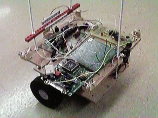
This paper describes the design and construction of a small autonomous robot for entry in the 1998 Fire Fighting Robot Competition. At the heart of the system is the 68HC12 microcontroller by Motorola. Program code to control the fire fighting robot is written in 68HC12 native assembly language. The system controls two optically isolated stepper motors for precision movement. Furthermore, the robot performs analog to digital conversion on 6 infrared sensors: 4 for wall proximity detection, one to detect floor markings, and one for candle detection. The 4 proximity sensors utilize heterodyne modulation of the IR signals to reduce the effects of ambient lighting. The extinguishing system is comprised of a large fan salvaged from a toy hovercraft, and a 3.5kHz tone decoder circuit is used to start the robot and gain bonus points.
The annual Fire Fighting Robot Competition sponsored by Trinity College has been an exciting event for several years. Robot hobbyists and professionals of all ages from all parts of the world gather to compete and show off their creations. The goal of the event seems simple: Navigate a model house floorplan, find a lit candle, and extinguish it. As simple as this may sound, it is an intricate process to construct a device which can accomplish such a task. There are a vast number of design options and operating techniques that can be explored.
As the contests web page states, a primary purpose of the contest is to "provide an incentive for the robotics community to develop what will be a practical application for a real-world robot". Although the contest is merely a simulation of a real-world scenario, it requires the designers to use practical techniques to create useful designs. The competition serves as an example of what robots can do on a larger scale.
In the first year of competition, there were only a few robots that were able to successfully find and extinguish the candle reliably. The more recent events, however, have yielded a larger number of successful entries. It appears, that the designs are becoming more sound as the robotics community learns which approaches work and which fail. Because of these improvements, the event has a higher level of competition. An entry that strives to perform well must be fast and reliable. This designers of this project aim to accomplish both these tasks.
Although the rules of the contest are lengthy and detailed, an overview will be given to provide a better understanding of the design approach used in this project. See the Rules Page (Appendix B) on the Trinity College web page for the full list of contest rules.
Figure 1 is a functional block diagram of the robot system. At
the heart of the robot is the 68HC12
microcontroller from Motorolla. The microcontroller is responsible
for sending signals to and receiving signals from the robot hardware.
First, the 68HC12 receives input from the calibration button before each
run. This allows the user to align the robot at a specific distance
from the desired wall to be followed. Once this has occured, the
68HC12 waits for a logic low from the tone-decoder. Then, the controller
outputs to the optoisolators to control the motor driver circuits.
The controller also reads values from the IR phototransistors in order
to detect walls and search for the candle.
Stepper Motors and Stepper Driver Circuit
When deciding how to move the robot through the house, the designers realized that precision movement would be necessary in order to avoid touching the walls and receiving penalties. In order to achieve the required precision in movement, it was decided that the robot would utilize stepper motors.
The main benefit of stepper motors is that they are able to turn a specific number of degrees for every step. A four phase stepper motor has four coils that, when energized in a specific sequence, rotate a driving magnetic field which, consequently, rotates a set of permanent magnets. These permanent magnets are attached to a rotor which drives an output shaft. Thus, by pulsing the coils in a certain sequence, a clockwise or counterclockwise movement can be attained.
The following table shows a typical stepping sequence for a four phase
stepper motor:
|
A change in the coil states (ie. changing from state 2 to state 3 as
shown above) results in a single step of the motor shaft. Direction
is easily controlled by running through the above sequence either forward
or backward. It should also be noted that the coils A and A' are
always oppositely charged, as are coils B and B'. By inverting the signals
going to coils A and B, the corresponding signals A' and B' can be attained.
Thus, only two control lines are required to place the motor into any one
of the 4 possible states. Even though this is an important consideration
for certain applications, the controller used in this implementation has
a sufficient number of lines to control each coil. Furthermore, because
two of the coils are always energized at any given time, the rotor is held
into place by the two magnetic fields and hence will not easily slip --
even when the motor is not turning. This is another benefit of stepper
motors. Figure 2 provides an internal diagram of a typical four phase
stepper motor.
The stepper motors used for this project were salvaged from surplus Epson printers. The steppers are designed to provide 1.8 degrees per step (or 200 steps per revolution) and supply a sufficient amount of torque. However, the current requirements of almost any motor are more than a digital output can provide. Because of this requirement, a transistor circuit is needed to drive the motor coils.
The circuit shown in Figure 3 is used to drive the motor coils.
Because there are a total of eight motor coils in the robot, eight of these
circuits are needed. The circuit functions by receiving a digital
input from the microcontroller. This signal is fed to an optoisolator in
order to separate the low-voltage, low-current microcontroller from potentially
dangerous signals in the motor driver circuit. In other words, the
optoisolator allows the 68HC12 to control the motors without any physical
connection to the driver circuit. The output side of the optoisolator
then drives the base of the TIP112 driver transistor. Just as the
stepper motors were, the TIP112 transistors were salvaged from the Epson
printers. The TIP112 power transistors are able to supply 50 watts
of power, which is more than sufficient to drive the stepper motor coils.
When the microcontroller outputs a digital low signal (logic 0), the output side of the optoisolator acts as an open circuit (ie. no current flows into the collector). The remaining current path is then from Vcc through the pull-up resistor and into the base of the TIP112 driver transistor. This effectively turns the transistor on so that current can flow from collector to emitter. Clearly, current will flow from the 7.2V battery, through the motor coil, into the collector of the TIP112, and to the emitter ground. Hence, when a logic 0 is sent from the 68HC12 to a given driver circuit, the corresponding coil will become energized. Inversely, when the microcontroller outputs a digital high signal (logic 1), current will flow from collector to emitter in the output of the optoisolator. This will restrict current from flowing into the base of the driver transistor -- causing it to be turned "off". When the driver transistor is "off", there is no path to ground and thus the coil will not be energized.
The current dissipating diode (or "free-wheeling diode") D1 is used so that the current stored in the motor coil does not damage the power transistor. When the transistor is turned off, the large magnetic field stored in the motor coil could generate a current spike through the collector to ground. The diode, however, will allow this potentially dangerous current to flow around the motor coil until it has been dissipated. The diode also helps to reduce the time it takes for the motor coil to switch from an "on" state to an "off" state. The speed at which a stepper motor can reliably rotate is relative to the amount of time it takes for a motor coil to switch states. By reducing the transition time, the stepper motor can be driven at higher frequencies resulting in a higher velocity. A small resistor in series with diode D1 has also been added to help reduce the transition time of the motor coil.
The shaft of each stepper motor is mounted directly to a 4" diameter rubber wheel. The wheels were purchased at a local hobby shop and provide a sufficient amount of friction with the floor of the house. In order to calculate how much the robot will move with each step of the motor, the following equation for arc length can be used:
Infrared Sensors and Sensor Circuits
In order for the robot to determine its position in the house, some kind of proximity sensing device is needed. After some consideration, an infrared system was chosen for its simplicity. Other types of sensors (specifically ultrasonic) do give higher degrees of accuracy when measuring distance; however, infrared remains a simple and sufficient solution at a lower price tag. Additionally, the infrared sensing devices are available locally.
Infrared phototransistors function by using light to stimulate the electrons in the base of a transistor. Simply put, when light falls onto the device, the transistor becomes "closed" and current is allowed to flow from collector to emitter. Similarly, when the device is in complete darkness, the transistor is "open" and the collector current is zero. The amount of collector current is directly related to the amount of light on the device.
Because the infrared component of ambient light (or normal room light) may change depending on several uncontrollable environmental factors, the ambient light alone cannot be used for proximity sensing. Rather, an infrared light emitting diode (IR LED) is used to provide a more usable level of IR to the phototransistor. When the IR LED is forward biased, IR light will emit out of the device and reflect off the white walls back to the phototransistor. Because light intensity falls off as a function of distance, the amount of IR sensed by the transistor is directly related to the distance to the reflecting surface. All transistors, however, have a limited operating region. Specifically, a phototransistor's collector to emitter voltage will only vary within a certain range of light intensities.
To prove that the IR sensors would be sufficient for proximity detection, a series of tests were performed and measurements were recorded. In each test, a phototransistor was biased with a different collector resistor to determine an adequate resistance value. The results of the tests were graphed as transistor voltage as a function of wall distance. Figure 4 shows these results.
The project nature requires that the sensors have good resolution at relatively close ranges. Although the 10k and 20k Ohm resistors gave a smooth range of values between 3 and approximately 16 inches, it was decided that a low-range cut-off of 3 inches would not suffice. The 5k Ohm resistor performed better in that it gave a lower cut-off point of approximately 2 inches, while the 1k Ohm resistor failed to detect the wall at approximately 5 inches. The measurements show that a 3k Ohm resistor provides the perfect bias: A moderately smooth change in transistor voltage occur between 1.5 and 8 inches. Because the critical robot movements occur in the 18 inch-wide hallways and the robot is 12 inches wide, the side sensors will be able to accurately determine the distance to each wall.
It should be noted, though, that the above graph reflects sensor measurements taken with a small flashlight illuminating the wall surface. Because a flashlight bulb can provide a large amount of IR, it was the first choice for the infrared source. It was later discovered that the flashlight bulbs would be a poor choice for two reasons. First, the bulbs have a slow on-off time, so slow that it is visible to the human eye. With the large number of sensor readings that the robot must make, the slow switching becomes intolerable. Second, the bulbs draw far too much current at approximately 1A per bulb. With 7 bulbs (one for each corresponding sensor), the current drain would become too much for a small mobile robot of this kind.
The solution was to repeat the above process using IR LEDs instead of flashlight bulbs, take measurements, and produce a similar graph. From this graph, the designers were able to determine that a 15k bias resistor would be needed to work well with the IR LED. Because the LEDs emit far less IR light than the flashlight bulbs, the phototransistors must be biased differently.
Initially, a simple proximity sensing solution was implemented using a IR LED and phototransistor pair. This method was adequate, but performed rather poorly when subjected to differing ambient light conditions. It was decided that an improved solution must be constructed. In order to cancel out the effects of ambient light, a form of heterodyne modulation of the IR signal is used. Figure 5 shows the demodulation circuit.
The circuit theory is straightforward. The 68HC12 uses one of the built-in pulse-width modulation (PWM) channels to strobe the base of a TIP112 power transistor and flash an IR LED at a frequency of 1kHz. The signal received at the phototransistor will be comprised primarily of a DC level (from ambient light), a 120Hz signal (from standard room lights), and the 1kHz signal emitted by the IR LEDs. The idea then is to filter out the unwanted signals and obtain only the 1kHz "carrier". The intensity of the 1kHz signal can then be used to give an accurate indication of how far the robot is from a certain wall in the house.
A 741 operational amplifier is used to create a bandpass filter for phototransistor signal. This circuit was designed around a high-pass filter from the AARL handbook. By adding a capacitor in the positive feedback path, the lower frequencies can be restricted. The result is a bandpass filter.
The output of the bandpass filter is the recovered 1kHz signal. However, this signal cannot be read directly by the analog to digital converter on the 68HC12 because it swings to negative voltages. To make this signal useful, the signal must be converted to a relative DC level (or intensity level). In order to do this, the output of the 741 is passed through a diode that acts as a half-wave recitifier. The result is a waveform comprised of only positive levels. This signal is then passed over a 47uF capacitor to ground in order to smooth the signal to a near-DC level. The 10k parallel resistor provides a current path for the voltage stored in the capacitor, so that the voltage can change rapidly. Because the filter may output signals greater than 5V, a 5V zener diode is used to clip the output at 5V.
By connecting the analog to digital input of the 68HC12 to the output of the filter, an accurate measurement of a wall distance can be obtained. Most importantly, the measurement will not be influenced by the amount of ambient light in the house.
As stated previously, there are 4 sensor channels that utilize the above-described modulation/demodulation technique. These correspond to the right, left, front, and back wall sensors. The floor sensor, however, need only be capable of determining if a white line is present. In other words, the floor sensor measurement is converted to a binary value (present, not present), and therefore modulation is not necessary.
The candle detection circuit also implements a phototransistor. However, because a candle emits a substantially large amount of IR, an IR emitter is not required. When the phototransistor is directly pointed at a lit candle, the collector to emitter voltage drops approximately 1.7V at a distance of 24 inches. Even at a distance of 3 feet, there is a significant drop in voltage to be detected by the microcontroller's A/D and to indicate the presence and direction of the candle. These specifications are within the requirements of the project. To further improve the directionality of the candle sensor and to improve its distance threshold, a reflective parabolic dish was placed around the candle sensor. By using a simple phototransistor for candle detection, the robot will be able to determine if the candle is present from the doorway of any room.
In order to obtain a 5% reduction in time, the robot is capable of detecting a 3.5kHz tone to begin its trials. The project designers hope that such bonuses may help the robot to be more competitive during competition. The tone decoder circuit is presented in Figure 6.
The circuit is based around two integrated circuits: An LM385 audio amplifier and the LM567 tone decoder IC. The LM385 is used to amplify the weak signal picked up by the condenser microphone, and the LM567 is used to filter the signal and provide a logic low when the signal is present.
An audio signal is picked up by a small condenser microphone and fed to the input of the audio amplifier. The LM385 is useful in that it requires only a single positive supply voltage, unlike most similar amplifiers. This reduces the need for an additional power supply -- a serious consideration for a small robot. The LM385 is designed to give a typical gain of 20, but the use of feedback may increase the gain to more than 100. The potentiometer between the output pin and the negative input pin supplies this feedback and allows the circuit to be adjusted.
After the audio signal is amplified, it passes through a filter capacitor (C4) and into the input pin of the LM567. The LM567 is precisely designed for the decoding of tones. The frequency of an internal local oscillator is set by a timing resistor Rt on pin 5 and a timing capacitor on pin 6. This operating frequency of the LM567 is approximately equal to this local oscillator frequency. As the part's data sheet states, the frequency can be obtained by choosing Rt and Ct such that
The Motorola 68HC12 Microcontroller
The advisors for this project indicated that the 68HC12 microcontroller by Motorola is to be used as the robot "brains". The 68HC12 is a 16-bit microcontroller with several useful features relevant to this project, including
Unfortunately, the Flash EEPROM array on the 68HC12 chip can only be reprogrammed 100 times. This is a serious limitation when designing, testing, and debugging program code. Because of this limitation, the project designers have attempted to keep the code simple so that it can fit into the 768 bytes of byte-erasable EEPROM. The byte-erasable EEPROM is more useful in that it can be reprogrammed 10,000 times. Ideally, as reliable and stable sections of the robot control code are completed, they could be programmed into the Flash EEPROM and used at a later time. However, the default programming utility (D-Bug 12) that allows programming of the byte-erasable EEPROM resides in the Flash EEPROM. Any programming to the Flash EEPROM array will remove the important debugging utility and make code development much more difficult. Ideally, a smaller programming utility could be developed to replace D-Bug12 and coexist in Flash EEPROM with other robot functions.
Program code to control the robot is written in the 68HC12's native assembly language. Another nice feature is that 68HC11 code can be compiled and executed on the 68HC12. See Appendix C for a listing of the current source code.
Because the floorplan is fixed and the placement of the candle can be
considered random, the robot can be programmed to traverse the house in
a specific room order. The entire program operation is straightforward:
Wait for the tone, then proceed to first room, if candle is present, locate
and extinguish it, otherwise proceed to the next room. Once the candle
has been successfully extinguished, the robot will return to the starting
location for a bonus reduction in time. Figure 7 shows a program
flowchart for this operation.
In order for the robot to accomplish the above tasks, it must first
navigate through the hallways in order to find a room. Ideally, the
robot must be able to find its way into a given room from any location
in the house. Figure 8 demonstrates how this is to be accomplished.
Simply put, the robot is able to follow a given wall by comparing sensor
readings with the calibration readings. If the robot determines that
it is too close to the specified wall, it sets the motor directions and
turns away from the wall. Similarly, if the robot is too far from
a wall, it will set the motor directions and turn toward the wall.
Although this may seem like a poor control method, the small steps of the
stepper motors provide a seemingly fluid robot movement. A relatively
simple means of navigating the entire house, then, is to simply follow
a given wall until a room has been entered. As mentioned before,
this condition can be detected when the floor sensor picks up the white
line marking the room doorway.
Once the robot has found its way into a room, it must then determine
if the candle is present. As stated previously, the sensors should
be capable of locating the candle from the doorway of any given room.
To ensure that the robot can scan the entire room contents, it first attempts
to drive 12 inches into the room. If it encounters the circle surrounding
the candle or travels all 12 inches, it will begin a counterclockwise sweep
to "look" for the candle. If the candle is present in the given room,
the robot will move toward it (if it is not already close enough) and blow
it out. Figure 9 demonstrates the Room subroutine and how the robot
behaves once it has entered a room. It should also be noted that
if the candle has already been extinguished, the robot will simply stop
at the doorway and back up to the facing wall.
Once the robot has processed all four rooms, it can then realign with a wall and follow that wall back to the starting point. Again, during the return trip, the robot does not enter the rooms looking for the candle.
By performing the tasks listed in the above three flowcharts, the robot is able to enter the house, locate the candle, extinguish it, and navigate back to the beginning. A series of tests were perfomed on the robot to see how it would perform with the candle in various locations in the house. 24 fixed candle locations were chosen and a series of 24 trials were conducted. Out of the 24 trials, the robot was able to successfully extinguish the candle 21 times. At the time of the trials, program code was still under development, and thus the robot only completed its return (without touching any of the walls) on 13 of the 21 attempts. The time taken for the robot to reach the candle and extinguish it ranged from 14 seconds in the first room to 49 seconds in the fourth room. With a 55% reduction in time, the worst case scenerio would be approximately 27 seconds per trial. These results demonstrate that the robot can accomplish all desired tasks while performing reliably.
The annual fire fighting robot competition is an interesting event that challenges the contestants to design a small robot that is capable of finding and extinguishing a lit candle. A solid and reliable design for this competition has been constructed and tested with promising results.
The two-wheel design allows the robot precision movement by using stepper motors while also keeping control simple. Proximity sensing is accomplished though the use of IR phototransistors. The devices work well in allowing the robot to determine how far it is from the walls in any given direction up to a distance of approximatley 6 inches. By modulating the IR emitters and passing the phototransistor output through a bandpass filter, the effects of ambient light can be greatly reduced. The two rechargable batteries (for the motors and logic circuits, respectively) have been tested under full load and are capable of supplying the robot with enough power to complete all three of its trials. By using a tone decoder to begin its trials, the robot will receive a 5% reduction in overall time. Furthermore, the program code written for the 68HC12 microcontroller is capable of moving the robot through the model house without touching any walls. It can enter each of the rooms, scan for the lit candle, and extinguish it if it is present. Once is has navigated the entire house and put out the candle, the robot will the navigate back to the starting position.
At this point in time, though, the primary task left to be completed is continued development of program code. In certain portions of the house, the robot does not move efficiently (that is, it comes quite close to hitting the walls). As the program code improves, though, the robots performance improves. The existing code (see Appendix C) does, however, successfully accomplish all necessary tasks for competition.
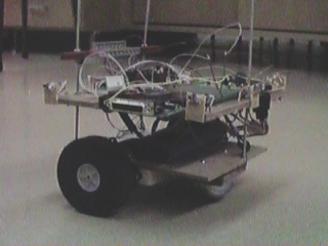
The existing robot chassis has evolved from an early prototype. Although the existing chassis serves its basic purpose of supporting the necessary hardware, the design can be improved. An improved chassis design could be lighter to create less torque on the stepper motors. This should result in a faster maximum speed and/or a longer battery usability. Also, an improved chassis could allow better placement of the circuitboards and wiring that is less disorderly.
By developing software to write programs into the byte-erasable EEPROM on the 68HC12, the authors could more effectively utilize the available memory. This would allow the D-Bug12 software to be replaced and would free up most of the flash EEPROM space for additional code development. The software listed in Appendix C nearly fills the entire array of byte-erasable memory, and this has become a serious limitation. With more code space available, the robot would be able to perform more rigorous computations on the incoming sensor data. Specifically, a more stable control method could be implemented.
;------------------------------------------------------------------
;
; FIRE FIGHTING ROBOT PROGRAM
; by Jason Plumb, Brent Short,
and John Walter
; EE3333 - Project Lab 3
; Spring 1998
;
; 3/24 Goes to every room and looks for the candle. If the
candle
; is present, it will go toward it and look for the circle.
When it
; reaches the circle it will turn the fan on and blow out the candle.
; It will not exit back out of the house once it blows out the
candle...
; it will just sit there.
;
; 3/28 - This code has been reduced in size
; * FWD, BK, and STOP
have been replaced with hard coded values
; * fwd_motors and bk_motors
routines have been implemented
;
; 3/31 - This is the reduced code with modulation added in.
; Specifically, it uses
PWM for the LED switch and the logic
; has been reversed
;
; 4/3 - Candle threshold is set for using flashlight reflector
; 4/4 - This has step count added back in and has been modified
; so that the robot will
detect the candle circle if it is
; < 12" from the door
; * This code has been modified so
that the robot aligns properly
; when entering the rooms.
This is done in the go_in routine
; Note: This code
needs serious reduction - it fills almost
;
all available byte erasable eeprom
; 4/9 - won't hit wall if candle is close -makes sure it has
; gone a certain distance
;------------------------------------------------------------------
; Begin program equates here
;------------------------------------------------------------------
RAMSTART: equ $0800
; Start of RAM for the HC12
PROGSTART equ $0D00
; Start of program in jump EEPROM
PORTA: equ $0000
; Address of port a on hc12
DDRA: equ $0002
; Data direction register for port A
PORTB: equ $0001
; Address of port b on hc12
DDRB: equ $0003
; Data direction register for port B
PORTE: equ $0008
; Address of port e on hc12
DDRE: equ $0009
; Data direction register for port E
ATDSTAT: equ $0066
ADR0H: equ $70 ;A/D
Converter Result Register 0
ADR1H: equ $72
;A/D Converter Result Register 1
ADR2H: equ $74
;A/D Converter Result Register 2
ADR3H: equ $76
;A/D Converter Result Register 3
ADR4H: equ $78
;A/D Converter Result Register 4
ADR5H: equ $7A
;A/D Converter Result Register 5
ADR6H: equ $7C
;A/D Converter Result Register 6
ADR7H: equ $7E
;A/D Converter Result Register 7
RAMSTRT: EQU
$0800 ; start of internal ram
RAMSIZE: EQU
$0400 ; Size of internal ram
STACK: EQU
RAMSTRT+RAMSIZE ; top of stack
ATDCTL2: equ $0062
ATDCTL3: equ $0063
ATDCTL4: equ $0064
ATDCTL5: equ $0065
ATDSTATH: equ $66 ;ATD
Status Register High
ATDSTATL: equ $67 ;ATD
Status Register Low
COPCTL: equ $16 ;COP Control
Register
COPRST: equ $17 ;Arm/Reset
COP Timer register
PWEN: equ $0042
; PWM enable register
PWPER0: equ $004C ; PWM period
channel for channel 0
PWCLK: equ $0040 ; PWM
clocks and concatenate (used to concat ch0 and ch1)
PWDTY0: equ $0050 ; PWM duty
cycle for channel 1
;----------------------------------------------------------------------
; Begin data segment
;----------------------------------------------------------------------
org RAMSTART
temp db $00
tempfw dw $00
tempw dw $00
NUM_STEP90 db $87
speed dw $05FF
led_speed dw $0000
sensor_diff db $0
rtmtr db $58,$3D
ltmtr db $58,$3D
;FWD db $58
;BK db $54
;STOP db $a7
; RAM variables used for holding sensor readings begin here
s0loff db $FF
s1loff db $FF
s2loff db $FF
s3loff db $FF
s4loff db $FF
s5loff db $FF
s6loff db $FF
s7loff db $FF
s0lon db $FF
s1lon db $FF
s2lon db $FF
s3lon db $FF
s4lon db $FF
s5lon db $FF
s6lon db $FF
s7lon db $FF
s1_close_thresh dw $0050
s2_close_thresh db $FF
s3_close_thresh db $FF
s5_close_thresh db $FF
s6_close_thresh db $FF
s2_far_thresh db $FF
s3_far_thresh db $FF
s5_far_thresh db $FF
s6_far_thresh db $FF
s2_center_thresh db $FF
s3_center_thresh db $FF
s5_center_thresh db $FF
s6_center_thresh db $FF
wall_status db $00
pwall_status db $00
abs_thresh db $00
; The absolute threshold for any given sensor
exist_thresh db $18
sens_addr dw $0072
; Parameter to follow_wall function
sens_far_thresh db $00
sens_close_thresh db $00
follow_wall db $00
;0=right, not zero = left
low_step
dw $00
;step count for lowest candle value
low_value db $00
;lowest candle value - init to $FF
old_y
dw $00
old_x
dw $00
; Artificial stack vars
abovect
db $00
extinguished db $00
stepct
db $00
old_rt
db $00
in_circle db $00
;----------------------------------------------------------------------
; Begin main program
;----------------------------------------------------------------------
org PROGSTART
;----------------------------------------------------------------------
; Initialization stuff here:
;----------------------------------------------------------------------
INIT_STUFF:
ldaa #$0
staa COPCTL
; Disable the COP watchdog timer
staa ATDCTL3
staa extinguished
staa stepct
staa in_circle
ldaa #$FF
staa DDRB
; Set direction for port B (all output)
staa PORTB
; Write initial PORT B value (unlock mot)
movb #%11101101, DDRA ; Set direction for A (outputs)
;ldaa ;PORTA
ldaa #%00001101
; Ensure that calibration LED and IR LEDs on and Fan is off
staa PORTA
; Put byte back on port A
movb #$80, ATDCTL2 ; Set up
ATD to function normally
;movb #$00, ATDCTL3 ; Select
continue conversion in BGND Mode
; Ignore FREEZE in ATDCTL3
movb #$01, ATDCTL4 ; Select
Final Sample time = 2 A/D clocks
; Prescaler = Div by 4 (PRS4:0 = 1)
;The next x lines set up RAM variables during init...
;that way, they aren't lost when we power down.
;(not used, hard coded)movb #$81, NUM_STEP90
;(speed is hard coded in the delay routine)
;movw #$1700, speed ; #$1D10, speed
; Speed variable
ldd #$003D
std rtmtr
std ltmtr
;movw #$003D, rtmtr
;movw #$003D, ltmtr
;movb #$40, s1_close_thresh ; Just hard coded for now
;movw #$01F6, steps_360 ; (was 1f8) (was 200)
;movb #$55, candle_thresh
; The next 4 lines set up and start PWM for modulating IR
LEDs
movb #$40, PWCLK
; Concat channels 0 and 1
movb #$03, PWEN
; Enable PWM
movb #$1F, PWPER0 ; Set
channel 0 period
movb #$10, PWDTY0 ; Set
channel 0 duty cycle
;movb #$00, stepct
;jsr INIT_STUFF
; Do initialization stuff
;----------------------------------------------------------------------
;end init
;----------------------------------------------------------------------
jsr WaitForTone
; Actually, wait for button
jsr Read
ldaa ADR6H
; Get right wall calibration value
ldab ADR2H
addd #$0A0A
; Add for close threshold (due to modulatioN)
staa s6_close_thresh ; Calculate and store thresholds
stab s2_close_thresh
subd #$1414
staa s6_far_thresh
stab s2_far_thresh
jsr wait_toggle
; Should turn it back on
jsr WaitForTone
; tone or button
movb #%00110011, PORTB ; Write initial value to port
B
basic:
;
ldy #$00FF
jsr fwdabit
movb #$FF, follow_wall ;left wall
jsr Follow
jsr RoomL
; First room (island)
jsr right_90
movb #$00, follow_wall ;right wall
jsr Follow
jsr RoomR
; Second room
jsr right_90
jsr Follow
jsr RoomR
; Third room
jsr right_90
jsr Follow
jsr RoomR
; Fourth (last) room
jsr left_90
ldaa #$FF
staa count_steps
ldaa #$FF
staa follow_wall ; Follow left wall out of house
staa done
jsr Follow
jsr Room
jsr right_90
ldy #$00DA
jsr fwdabit
jsr Follow
quit: movb #%11111111, PORTB
stop: bra stop
;----------------------------------------------------------------------
; This will wait for the tone to be present for a given period
of time
; before continuing. If the button is pressed, it will also
exit
;----------------------------------------------------------------------
WaitForTone:
;stx old_x
ldx #$3000
Tone2: ldaa PORTA
bita #%00000010
; Check for button
bne ToneExit
bita #%00010000
beq TonePres
; The tone is present
bra WaitForTone
TonePres: dex
beq ToneExit
bra Tone2
ToneExit:; ldx old_x
; Artificial stack
;----------------------------------------------------------------------
; This will toggle the status of the calibration LED
;----------------------------------------------------------------------
ToggleCLED:
ldaa PORTA
eora #%00000100
staa PORTA
;ldy old_y
; Artificial stack
rts
;----------------------------------------------------------------------
;wait $100 delay cycles - used for calib. LED - then go on to toggle
;----------------------------------------------------------------------
wait_toggle:
;sty old_y
; Artificial stack
ldy #$0100
wtlp1: jsr DELAY
; Wait before turning LED back on
dey
bne wtlp1
bra ToggleCLED
;----------------------------------------------------------------------
Read: movb #%01010100 , ATDCTL5
; Initializes ATD, MULT=1 (do conversions on AN0-AN7)
; Run conversions
on subsequent channels
WTCONV: BRCLR ATDSTATH,#$80,WTCONV ; Wait for Sequence
Complete Flag
rts
;-----------------------------------------------------
; This will follow the right or left wall until the floor
; sensor is detected
;-----------------------------------------------------
Follow:
ldaa stepct
; Used to go fwd every 3rd step
cmpa #$03
; If A is not equal to 3
bne Follow_1
; Then jump to follow1
movb #$00, stepct
; Otherwise, reset stepct
bra Follow2
; And jumpt to follow2 (go 1 step fwd)
Follow_1:
inca
; Increment A
staa stepct
jsr Read
ldaa ADR0H
;floor sensor
cmpa #$80
bhi no_line
jmp left_motor
no_line:
ldaa ADR3H
; Get value of front sensor (1 = 3 temp)
cmpa #$50 ; was 70
; Compare to close threshold
blo Follow1a
; If we didnt' "hit" a front wall, branch
jsr right_90
bra Follow
Follow1a:
ldaa follow_wall
; 0 for right wall, 1 for left
beq wall_right
; If zero, follow right wall
ldab ADR2H
; Otherwise, get left sensor value
cmpb s2_far_thresh
; Compare to the far threshold
bhi not_too_far
; If we're higher than far thresh, we're ok so far
bra foll_1bC
not_too_far:
; Not too far from left wall
cmpb s2_close_thresh
; Compare to the left close threshold
blo Follow2
; If lower than close thresh, just go fwd
bra wall_rtC
wall_right:
; If here, we're following right wall
ldab ADR6H
; Get front right sensor value
cmpb s6_far_thresh
; Compare it with far thresh
bhi Follow1b
; If higher, we're ok
wall_rtC: jsr left_motor
; Otherwise, turn in one step
bra Follow
Follow1b:
cmpb s6_close_thresh
; Compare sensor value to close threshold
blo Follow2
; If higher, we're aligned and can go fwd
foll_1bC:
jsr right_motor
; Otherwise, we need to turn away
bra Follow
Follow2:
jsr fwd_motors
; Set up motor directions for both fwd
jsr GO
; Go forward 1 step
bra Follow
; Keep following
;----------------------------------------------------------------------
; This will set the directions of the motors to pivot left
;----------------------------------------------------------------------
piv_left_motors:
movb #$58, rtmtr
movb #$54, ltmtr
rts
;----------------------------------------------------------------------
; This will set the directions of the motors to pivot right
;----------------------------------------------------------------------
piv_right_motors:
movb #$54, rtmtr
movb #$58, ltmtr
rts
;----------------------------------------------------------------------
; This will set the directions of both motors to fwd
;----------------------------------------------------------------------
fwd_motors:
ldaa #$58
staa rtmtr
staa ltmtr
rts
;----------------------------------------------------------------------
; This will set the directions of both motors to bk
;----------------------------------------------------------------------
bk_motors:
ldaa #$54
staa rtmtr
staa ltmtr
rts
;----------------------------------------------------------------------
; This will move just the right motor forward. Used in turning
;----------------------------------------------------------------------
right_motor:
movb #$58, rtmtr
movb #$a7, ltmtr
bra lmgo
;----------------------------------------------------------------------
; This will move just the left motor forward. Used in turning
;----------------------------------------------------------------------
left_motor:
movb #$58, ltmtr
movb #$a7, rtmtr
lmgo: jmp GO
;rts
;----------------------------------------------------------------------
; This will turn the car 90 degrees left or right
;----------------------------------------------------------------------
left_90: jsr piv_left_motors
;movb #$58, rtmtr
;movb #$54, ltmtr
bra all_set
right_90: jsr piv_right_motors
;movb #$54, rtmtr
;movb #$58, ltmtr
all_set: ldy #$0081
; Load Y with # of steps in 90 deg (NUM_STEP90)
loop_90: jsr GO
dey
bne loop_90
rts
;----------------------------------------------------------------------
; Goes forward or backward a bit depending on the value passed
in Y
;----------------------------------------------------------------------
;bakabit: jsr bk_motors
; bra bakabl
fwdabit: jsr fwd_motors
bakabl: jsr GO
dey
bne bakabl
rts
;----------------------------------------------------------------------
;Room Routine - This is what the robot does when it enters the
room
;----------------------------------------------------------------------
RoomL: jsr right_motor
bra into
RoomR: jsr left_motor
bra into
Room: jsr fwd_motors
into: movb #$00, PWEN
; Disable PWM (turn off IR LEDs)
rm1: ;jsr go_in
; Go into the room
;------------------------------------------------------------------
; go_in will move the robot into the room from the doorway
; It will exit out when it goes 12 inches or detects the candle
; circle on the floor
;------------------------------------------------------------------
go_in:
ldaa rtmtr
staa old_rt
; Preserve the original rt mot direction
go_o_line:
ldaa old_rt
cmpa #$58
bne go_o_lineL
jsr right_motor
bra go_o_line1
go_o_lineL:
jsr left_motor
go_o_line1:
jsr GO
jsr fwd_motors
jsr GO
jsr Read
; Read sensors
ldaa ADR0H
; Get floor sensor
cmpa #$80
; Compare with the floor threshold
blo go_o_line
; Keep going fwd until line disappears
ldaa extinguished ; Not
used (yet)
beq look
jmp leave
look: ldy #$00DA
; Should be 12 inches
; jsr
fwd_motors ; Set motor direction to fwd
go_in_al: jsr GO
; Go fwd 1 step
jsr Read
; Read sensors
ldaa ADR0H
; Get floor sensor
cmpa #$80
; Compare with line
blo go_bail
; If line found, we need to bail
dey
bne go_in_al
bra turn
go_bail:
ldaa #$FF
staa in_circle
jsr GO
dey
cpy #$0050
bhi go_bail
;ldy #$006C
;jsr fwdabit
;rts
turn: movb #$FF, low_value ; Init
strongest candle reading (lowest #)
jsr piv_left_motors ; Set up motor
directions for a left pivot
ldy #$01F6
; Y gets number of steps in a 360 deg turn
T360: jsr Read
; Read sensor values
ldaa ADR7H
; Get candle sensor value
cmpa low_value
; compare with the low_value
bhi not_stronger
; If higher, skip
staa low_value
; Otherwise, store as new low value
sty low_step
; Store Y into the low_step count var
not_stronger:
jsr GO
; Do one step CCW
dey
; Decrement step counter
bne T360
; If we haven't done a 360, keep going
; If here, we've done a whole 360
ldaa low_value
; Otherwise, get the lowest value
cmpa #$55
; Compare to candle threshold
bhi leave
; If higher, then candle not in room
jsr piv_right_motors ; Set up motor directions
for a right pivot
ldy low_step
ldab #$0C
aby
; Add $0C to Y to "fix" turn
turn_back:
jsr GO
dey
bne turn_back
jsr fwd_motors
ldx #$0000
FoundIt:
ldaa in_circle
bne fan_on
inx
jsr GO
; Step forward one step
jsr Read
; Read sensors
ldaa ADR0H
; Check floor sensor
cmpa #$80
; Compare with threshold
bhi FoundIt
; If higher, need to keep going fwd
fan_on: ldaa PORTA ; If we're
here, we hit candle circle
anda #%11110111
; Make fan turn on (reverse logic)
staa PORTA
jsr wait_toggle
; Keep fan on for ~ 1/2 sec
ldaa PORTA
oraa #%00001000
staa PORTA
; Turn fan back off
staa extinguished ; a != 0
jsr bk_motors
inx
back: jsr GO
dex
bne back
jsr piv_left_motors
ldy low_step
straight:
jsr GO
dey
bne straight
;jmp quit
leave:
movb #$03, PWEN
; Turn IR LEDs on before backing to wall
;jmp Back_to_wall
;rts
;----------------------------------------------------------------------
;backs until it sees a wall
;----------------------------------------------------------------------
Back_to_wall:
jsr bk_motors
; Set up motor directions for backward
no_wall: jsr GO
jsr Read
ldaa ADR4H
cmpa #$70
blo no_wall
rts
;----------------------------------------------------------------------
; This routine moves both motors one step
; The current state of the motor does not matter
;----------------------------------------------------------------------
GO: clc
; clear carry bit
ldab PORTB
; read the current motor byte
andb #%11110000
; Mask off right stepper bits
jsr rtmtr
; carry out shift
bcc NEXT1
; If we didn't carry, skip to NEXT1
orab #%00010000
; If we carried, set LSB of this nibble
NEXT1: bitb #%00001000
; check if we overflowed right
beq NEXT3
; if not, branch
eorb #%10001000
; if so, fix it
NEXT3: stab temp
; store right motor nibble in temp
clc
; clear carry
ldab PORTB
; read the current motor byte
andb #%00001111
; Mask off left stepper bits
jsr ltmtr
; carry out shift
bcc NEXT4
; if didn't carry, skip to NEXT4
orab #%00001000
; if carried, fix it
NEXT4: bitb #%00010000
; check if overflowed left
beq NEXT2
; if not, branch
eorb #%00010001
; if so, fix it
NEXT2: orab temp
; combine the two motor nibbles
stab PORTB
; send out to motor driver
jsr DELAY
rts
;----------------------------------------------------------------------
; This delay routine is used for delaying between steps
;----------------------------------------------------------------------
DELAY: xgdx
;(exchange X and D to save X) stx old_x
ldx #$1200
; Load X with speed var (used for delaying)
dloop: dex
; Decrement X
cpx #$0000
; If X != 0
bne dloop
; Loop again
xgdx ;(exchange X and D to save X) ldx
old_x ; Fake stack
eof: rts